Table of contents
Specifying the wrong hole type for fasteners directly inflates machining costs and ruins part assemblies. Misunderstanding the structural and manufacturing differences between counterbore and countersink holes leads to expensive scrap, weakened thin-wall components, or protruding screw heads that cause mechanical interference. We analyzed thousands of CNC machining projects at RapidDirect to break down the exact cost drivers and load-bearing realities of these two standard hole types. For design engineers and procurement teams needing to lock in the right standard fasteners and dimensioning callouts, here is the technical breakdown to optimize your next DFM review.
Core Differences: Counterbore vs Countersink
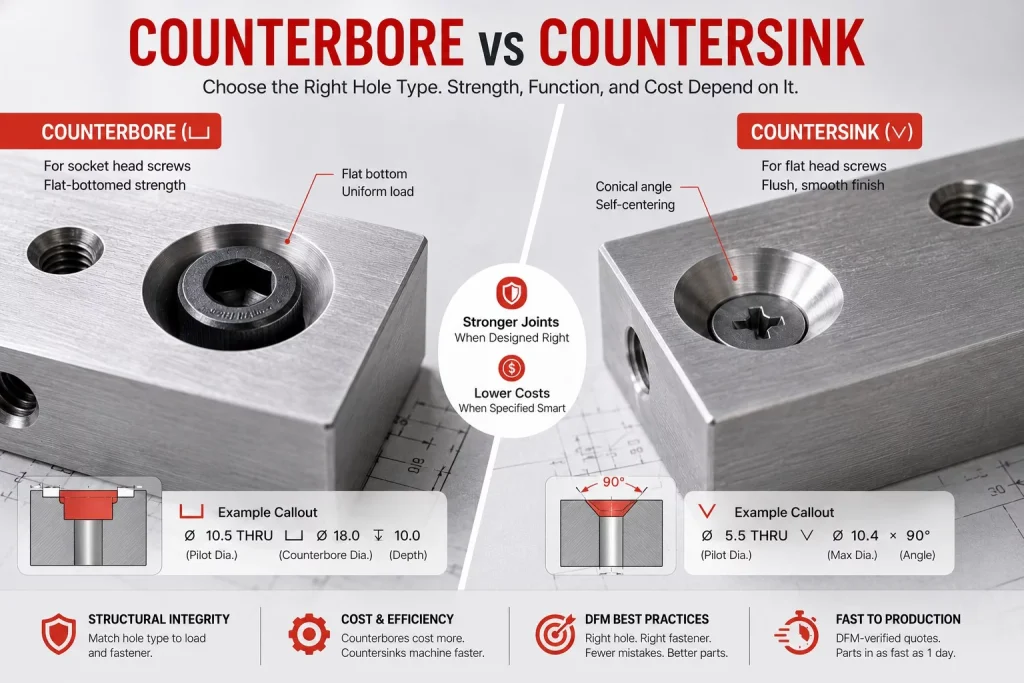
When deciding between a counterbore vs countersink, the choice dictates the fastener type, the machining time, and the structural integrity of the joint.
| Feature | Counterbore (⌴) | Countersink (⌵) |
| Geometry | Cylindrical, flat-bottomed cavity with straight walls. | Conical, V-shaped cavity. |
| Standard Fasteners | Socket head cap screws, hex bolts. | Flat head screws, oval head screws. |
| Primary Use Case | Heavy structural loads, high torque, holding washers/O-rings. | Flush surfaces, sheet metal, aerodynamics, consumer aesthetics. |
| Load Distribution | Uniform axial load on a flat surface. Excellent anti-vibration. | Radial and axial forces. Wedge shape creates outward stress. |
| Required CNC Tooling | Pilot drill, followed by a flat-bottom end mill or counterbore tool. | Standard single-flute or multi-flute countersink drill bit. |
| Cost & Machining | Higher cost. Requires strict depth control and multiple passes. | Lower cost. Fast single-step processing. Ideal for large batches. |
| Thin Wall Suitability | Poor. Removes too much base material, weakening the part. | Excellent. The standard choice for sheet metal enclosures. |
What is a Counterbore Hole?

A counterbore hole is a cylindrical, flat-bottomed recess machined into a part to enlarge the opening of a pre-existing hole. The counterbore definition centers on its purpose: allowing the head of a cylindrical fastener to sit completely flush with or below the surface of the workpiece.
This geometry provides a perfectly flat bearing surface for the fastener. You can easily stack lock washers, flat washers, or sealing O-rings inside the cavity. Because the clamping force is entirely axial, a counterbored hole is ideal for heavy machinery, automotive structures, and automated assembly fixtures experiencing high torque and vibration.
Counterbore Symbol and Callout
In technical drawings, precision is critical to avoid manufacturing errors. The standard counterbore symbol is ⌴, which represents the flat-bottomed shape.
A standard counterbore callout on a manufacturing print follows ASME Y14.5 rules. It requires three distinct parameters: the pilot hole diameter, the counterbore diameter, and the counterbore depth.
Example Callout: ∅ 10.5 THRU ⌴ ∅ 18.0 ↧ 10.0
This tells the machinist to drill a 10.5 mm through-hole, then machine an 18.0 mm diameter counterbore to a depth of 10.0 mm.
What is a Countersink Hole?

A countersink hole features a conical, V-shaped recess machined at the top of a pilot hole. The primary goal of countersinking is to allow a countersunk screw (like a flat head or oval head) to sit perfectly flush with the exterior surface.
This creates a smooth, aerodynamic finish with no protruding hardware. It is the standard fastener choice for consumer electronics, aerospace exterior skins, and thin sheet metal fabrication. Because the screw head is angled, it naturally self-centers during assembly, making multi-part alignment much easier.
Countersink Symbol and Callout
The standard countersink symbol is ⌵, visually mimicking the V-shape of the hole.
A correct countersink callout requires the pilot hole diameter, the maximum outer diameter of the countersink, and the specific included angle. Matching the angle to the screw is mandatory, or the fastener will not seat properly.
Example Callout: ∅ 5.5 THRU ⌵ ∅ 10.4 × 90°
This instructs the manufacturer to drill a 5.5 mm through-hole, followed by a countersink with a top diameter of 10.4 mm and a 90-degree angle.
Engineering and Procurement Considerations
CNC Machining Cost Drivers
When evaluating countersink vs counterbore for procurement, machining time directly impacts your unit price. Counterbore holes are more expensive to produce. The CNC mill must drill a pilot hole, switch to a counterbore drill or flat-bottom end mill, and carefully control the Z-axis to hit the exact depth tolerance.
Countersunk holes are much faster to machine. A standard countersink drill bit can plunge into the material rapidly. For large volumes of sheet metal parts, choosing countersinks significantly drives down your total cost of ownership.
Pro Tip: You can calculate these cost differences instantly. Upload your STEP file to RapidDirect’s quoting engine to get a free DFM analysis. The platform automatically detects your hole geometries and provides a real-time price based on our 1-day CNC machining capabilities.
[cta]
Load and Stress Distribution
You must match the hole type to your mechanical load. In a counterbore, the socket head cap screw pulls straight down. The clamping force is 100% axial, spreading evenly across the flat bottom.
In a countersink, the angled head acts like a wedge. As you tighten the screw, it creates radial forces that push outward against the walls of the part. If you apply high torque to a countersink in brittle plastics or thin metals, the material will crack or deform.
Standard Countersink Angles
Never guess the angle of your countersink dimensions. Different regions and industries use strict standards for countersink angles:
- 82 Degrees: The standard for Imperial / ASME fasteners.
- 90 Degrees: The standard for Metric / ISO fasteners.
- 100 Degrees: The standard for aerospace components and very thin sheet metal.
- 60, 110, and 120 Degrees: Specialty angles for specific hardware or pipe fittings.
Dimensional Reference Charts
Standard Metric Counterbore Size Chart
Use this counterbore dimension chart as a baseline for standard ISO socket head cap screws.
| Metric Screw Size | Pilot Hole (Clearance) | Counterbore Diameter | Counterbore Depth |
| M3 | 3.4 mm | 6.5 mm | 3.4 mm |
| M4 | 4.5 mm | 8.0 mm | 4.4 mm |
| M5 | 5.5 mm | 10.0 mm | 5.4 mm |
| M6 | 6.6 mm | 11.0 mm | 6.4 mm |
| M8 | 9.0 mm | 15.0 mm | 8.6 mm |
Standard Metric Countersink Size Chart
Use this countersink dimension chart for standard ISO 90° flat head screws.
| Metric Screw Size | Pilot Hole (Clearance) | Max Countersink Outer Diameter | Included Angle |
| M3 | 3.4 mm | 6.3 mm | 90° |
| M4 | 4.5 mm | 8.3 mm | 90° |
| M5 | 5.5 mm | 10.4 mm | 90° |
| M6 | 6.6 mm | 12.4 mm | 90° |
| M8 | 9.0 mm | 16.5 mm | 90° |
DFM Best Practices for Machined Holes

1. Do Not Mix Fasteners and Hole Types
Placing a flat head screw into a counterbore creates a tiny, unstable point of contact, destroying the joint’s strength. Placing a socket head screw into a countersink leaves the head completely exposed and unsupported. Always align your standard standard counterbore sizes with the exact fastener.
2. Protect Thin Walls
Avoid deep counterbores in thin materials. Removing that much base material compromises the part’s structural integrity. If you are working with thin sheet metal enclosures, a countersink is the structurally superior choice.
3. Always Specify the Pilot Hole
A drill and counterbore process requires a pilot hole to guide the tool and prevent the drill bit from walking. If your CAD file omits the pilot hole, it will trigger a DFM error, delaying your production schedule.
4. Account for Spotface Holes
A spotface hole is a variation of a counterbore. It is extremely shallow. Its only purpose is to machine away a rough cast or forged surface to provide a flat, smooth seating area for a bolt, rather than hiding the bolt head entirely.
Optimize Your Next Assembly
Choosing the correct hole geometry prevents structural failures, eliminates assembly interference, and keeps your machining budget in check. Use countersinks for sleek, flush aesthetics in thin materials. Rely on counterbores for heavy-duty, high-torque joints that demand maximum clamping force.
When you are ready to move from design to production, do not wait days for a manual quote. Upload your CAD files to the RapidDirect instant quoting platform today. Our automated DFM system will verify your hole tolerances instantly, and our manufacturing network can deliver precision CNC machined parts in as fast as one day.
[cta]
Frequently Asked Questions
A clearance hole simply allows the threaded body of a fastener to pass through without catching on the material. A counterbore enlarges the top of that clearance hole so the head of the fastener can sink below the surface.
Yes. The geometry is identical. The only difference is the depth dimension on the print. A spotface only cuts deep enough to create a flat seating surface on rough material.
Yes. Surface finishes like hard anodizing add material thickness to the walls of the hole. If you require tight tolerances for bearing fits inside a counterbore, you must specify the dimension as “post-plating” or plug the hole during finishing.
Countersunk screws generate outward radial stress as they are tightened. If the plastic is brittle or the hole is too close to the edge of the part, this wedging action will split the material.